HAM DIY – Easy VHF/UHF RDF Loop project
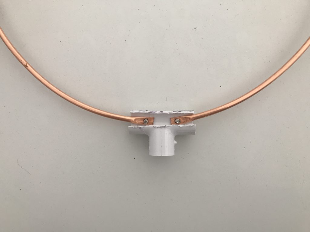
Here is a *very* easy little DIY ham project for Radio Direction Finding (RDF). Credit should be given to the Tri-City Amateur Radio Club P.O. BOX 552 Groton, CT 06340 – for their “Simple Loop Antenna for RDF“, in particular the idea to cut away a section of a 1/2” PVC “T” connector to make it easier to mount the loop. That works very well indeed and I am always going to take function over appearance. It works and I can cover it with tape if it bothers me. 🙂
I generally followed their layout, but added a few tweaks.
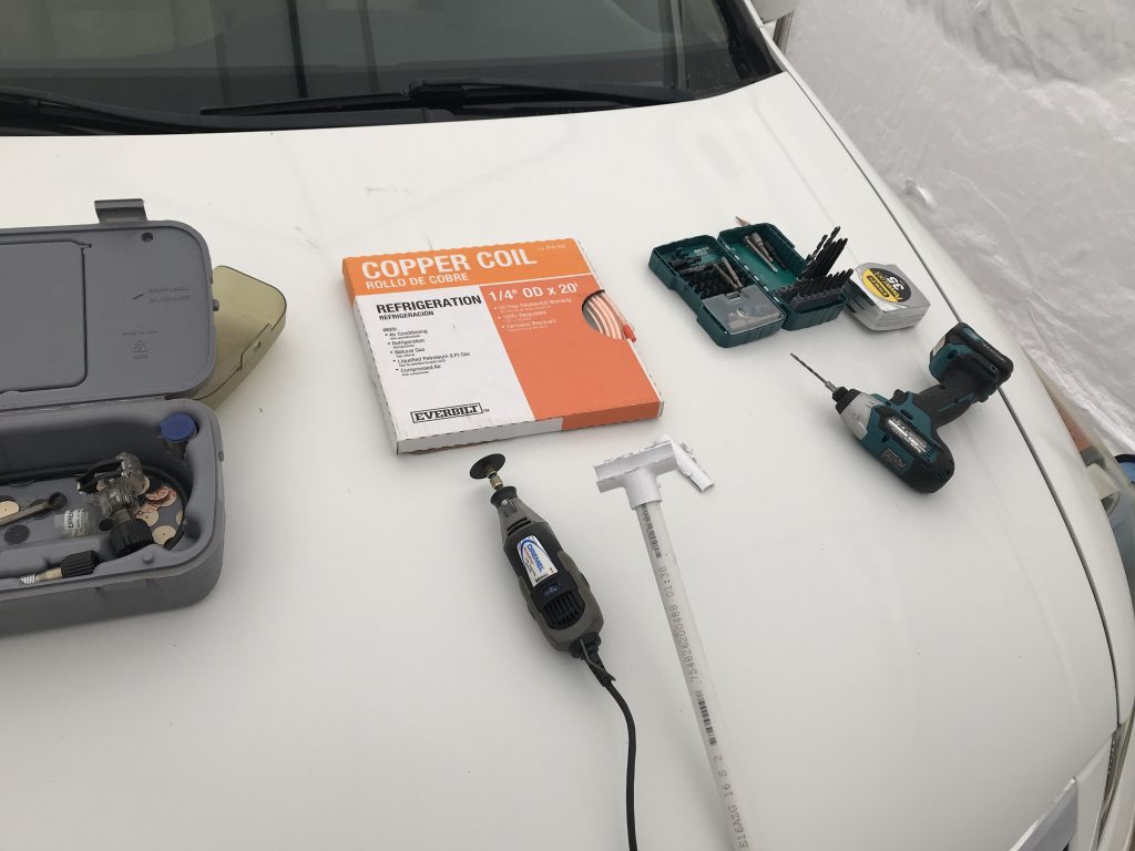
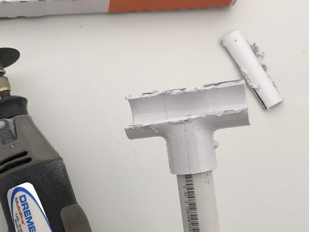
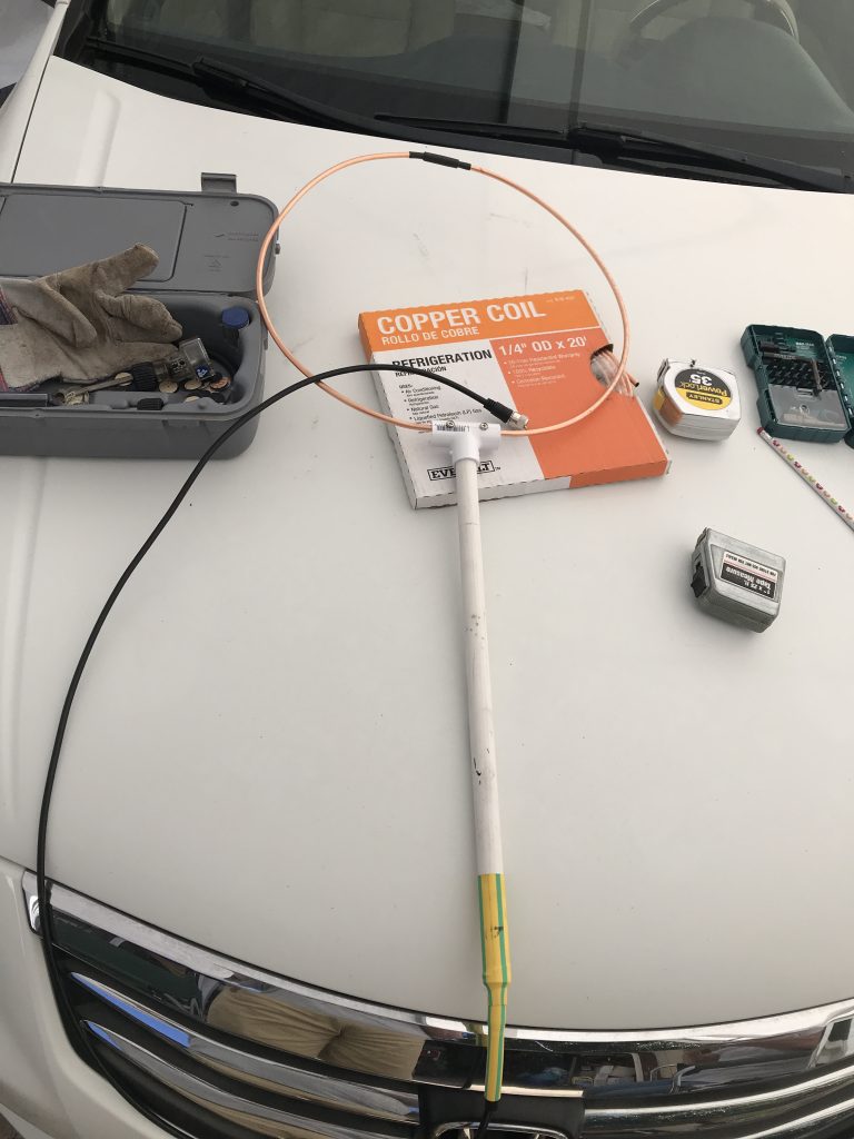
I had the necessary PVC from another project but did have to visit our local Home Depot to pick up some 1/4″ Copper tubing for this project. Here, I had just cut out a cross section of the PVC “T” – good old Dremel tool made short work of each and every cut associated with this project. Also have out the cordless drill and bits.
I honestly wouldn’t have thought of doing it this way myself – all credit to tricityarc.net for this one!
It certainly wasn’t a “precision” job, but got it done in a hurry. We were working out on the driveway and it was well over 90 out there so I was kind of “moving right along” with this project.
I really could have cleaned this up with a file and possibly spray painted it – but again, I was after both “easy” and practicing Function over Form.
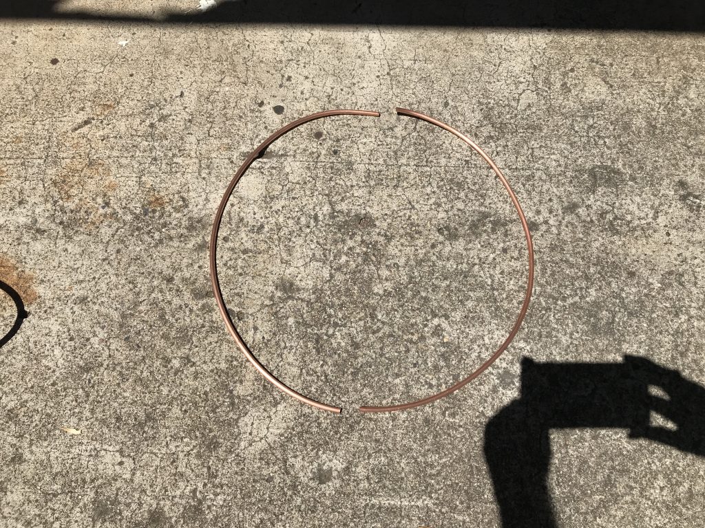
Each side of my loop is right at 20″ in length. Quite a bit larger than the one linked, but hey, I can still just stick it out the window without a problem. (It will be connected to a Step Attinuator between the antenna and radio for close in work).
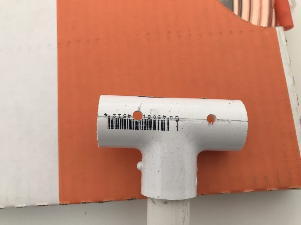
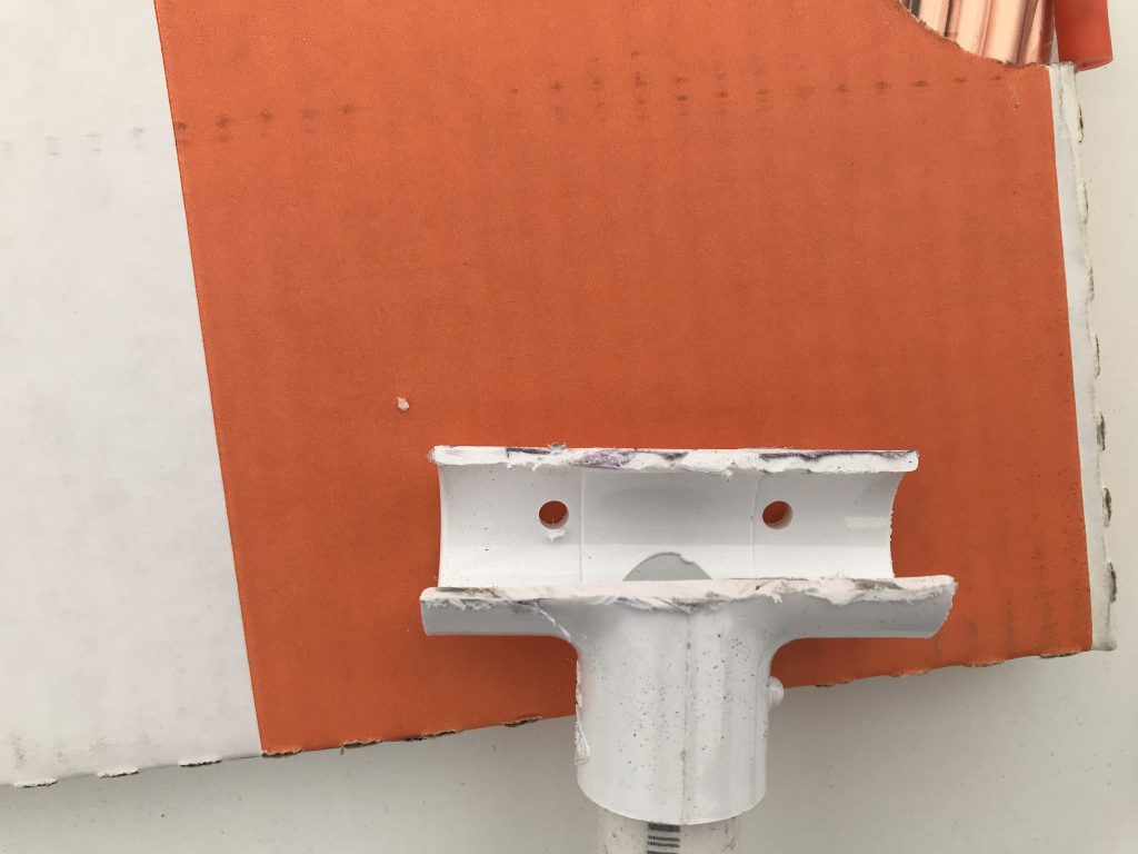
I used my concrete vice, (driveway with XYL standing on the tubing), and a hammer to flatten the bottom ends – then drilled them with the 3/16ths bit after punching them to get a start and not slip off.
In the above shot I just kind of pre-assembled the parts together to show Heidi what I was doing. Since she has had her General license for a few years now, she could appreciate how it was going to work when completed.
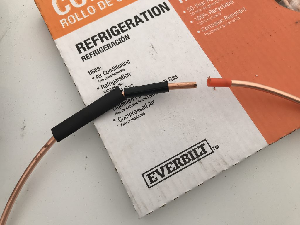
Mr. Dremel tool cut the “plug end” off of the end cap that came with the roll of 1/4″ tubing – making it a very small plastic “tube” which is exactly the right size/diameter to hold the two halves of the antenna about 1/2″ apart as required by this kind of loop. I found another piece of hard plastic tubing just the right diameter to fit over that – and a nice piece of shrink tubing to kind of lock everything down.
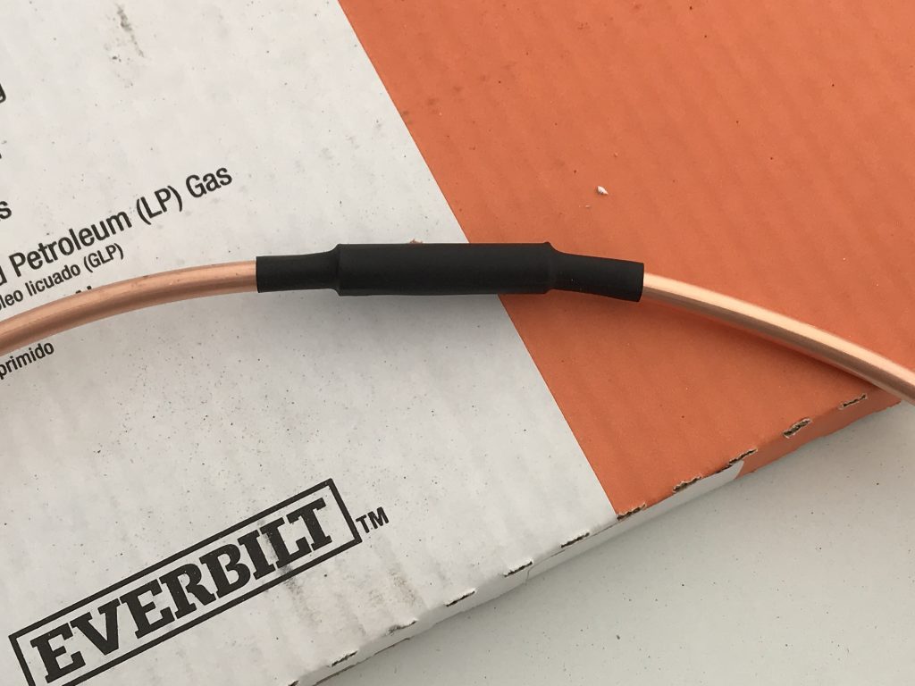
Heidi had to go find the heat gun for me, after that it only took a few seconds to get the top of the loop assembled and looking pretty good.
With Heidi’s help holding the bolts, I got the two nuts tightened down over the antenna elements and O ring connectors from the coax shield and center conductor very snug indeed. Prior to inserting the Coaxial cable, I had run quite a selection of shrink tubing of various sizes, (primarily left-overs from previous projects), which were used with Mister Heat Gun to form a kind of stress relief and “handle” at the lower end of the antenna. I believe it should stand up to fairly rough treatment for a very long time.
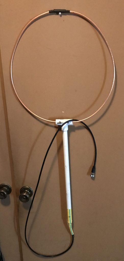
Forming what is essentially a quarter wave loop for 2 meters and a half wave loop for 70 centi-meters, it really is large for VHF/UHF but should pull in anything above the noise floor. I do intend to test its resonance with our MFJ-269C analyzer later on. For RDF many T-hunters have great success with 1/10th wavelength antennas *absolutely* build for receive only. That would put each element for 2 meters at about 8 inches and be very portable indeed.
I note it is a bit “Oval” shaped hanging there but that simply isn’t a problem to fix.
I might point out we were both taking it *very* easy, plus took a break and went back in the house for about 1/2 hour to cool off, the total time expended on this one was still less than three hours. (Closer to 2.5 hours). Given the help of my YL, it was FUN!
73, dave/W6TUX
UPDATE: This antenna turned out to be *VERY* resonate on 2 meters this first evening. Listening to a network on an HT the receiver was pegged regardless of antenna position. The repeater was on Otay Mesa, about 20 miles from our QTH down close to the border with Mexico. If you build a loop this large, you will definitely want to put an attenuator, either step or offset, in line between the antenna and radio.