HAM DIY – Foldable VHF Measuring Tape Yagi Revisited
I actually did this project back in July of 2018, but our Granddaughter was very close to giving birth to our first Great Grandchild, (who actually came to us on 2 August of that year). While the narrative is written in “current” form, I am merely copying/pasting from my old notes taken on a computer while the project was still in progress. 😉
July 21st, 2020
I am following one of several different designs found on the internet for a portable/foldable hand held Yagi antenna to use for direction finding, etc., in the “field”. The one I am following closest, because I really liked the recommendation to cut 1/2″ “Keepers” off the PVC pipe AS found here: http://www.instructables.com/id/Radio-Direction-Finding-Antenna-for-VHF/
I expect my end result to be a bit different, but generally the dimensions I followed on this first one pretty well match that link.
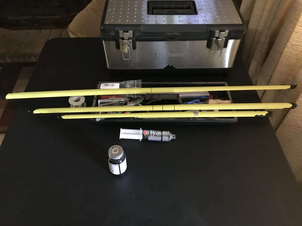
I started by taking apart a 25′ Harbor Freight tape measure, (the wider kind), then cutting elements for the yagi’s reflector, driven element, and director. Had enough to create two more sets of reflector and driven elements, but will have to take apart another to get the directors for them.
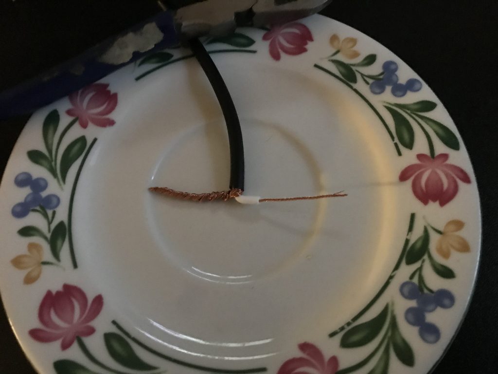
Here I have split the driven element in half, and scraped/sanded off the paint where I will be soldering each of them.
Each end has been trimmed to kind of round them, then dipped multiple times in liquid electrical tape to protect others from being poked by sharp edges.
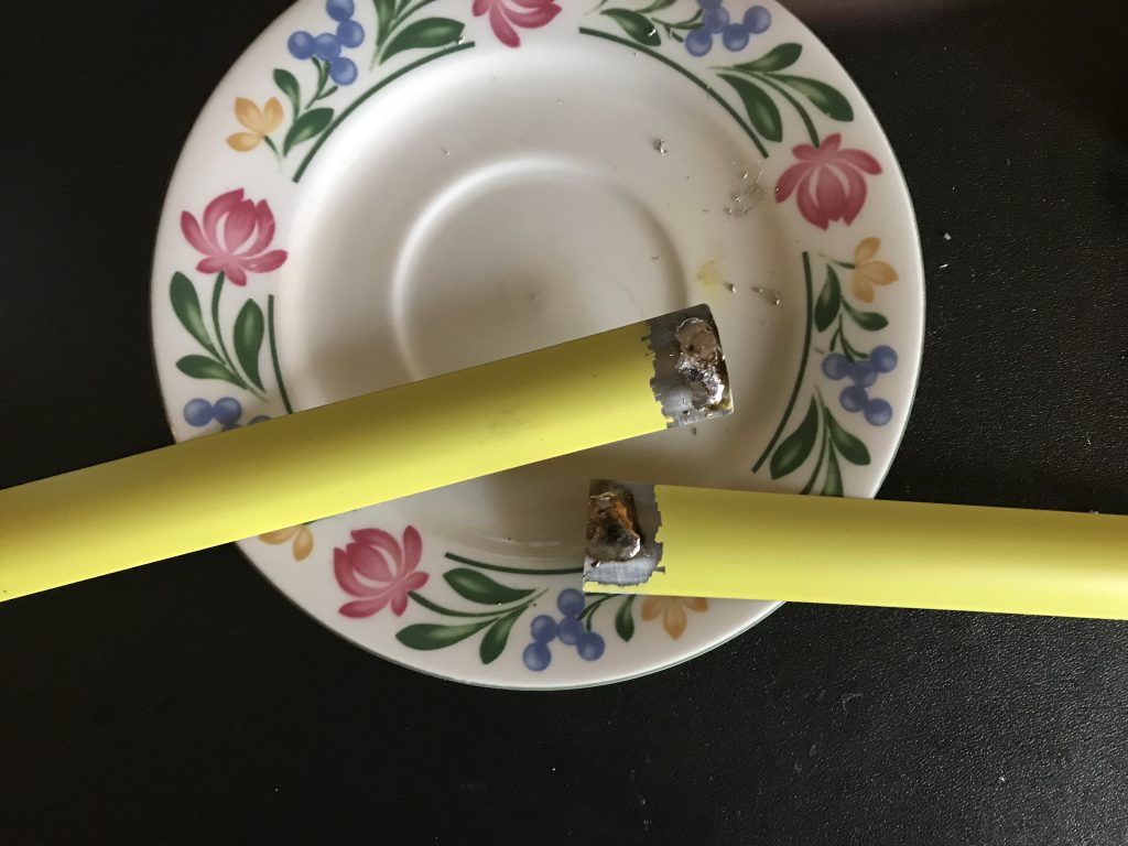
Here I have tinned the spots on the driven elements where I will later be soldering a hairpin match and the center lead and shield to the associated element.
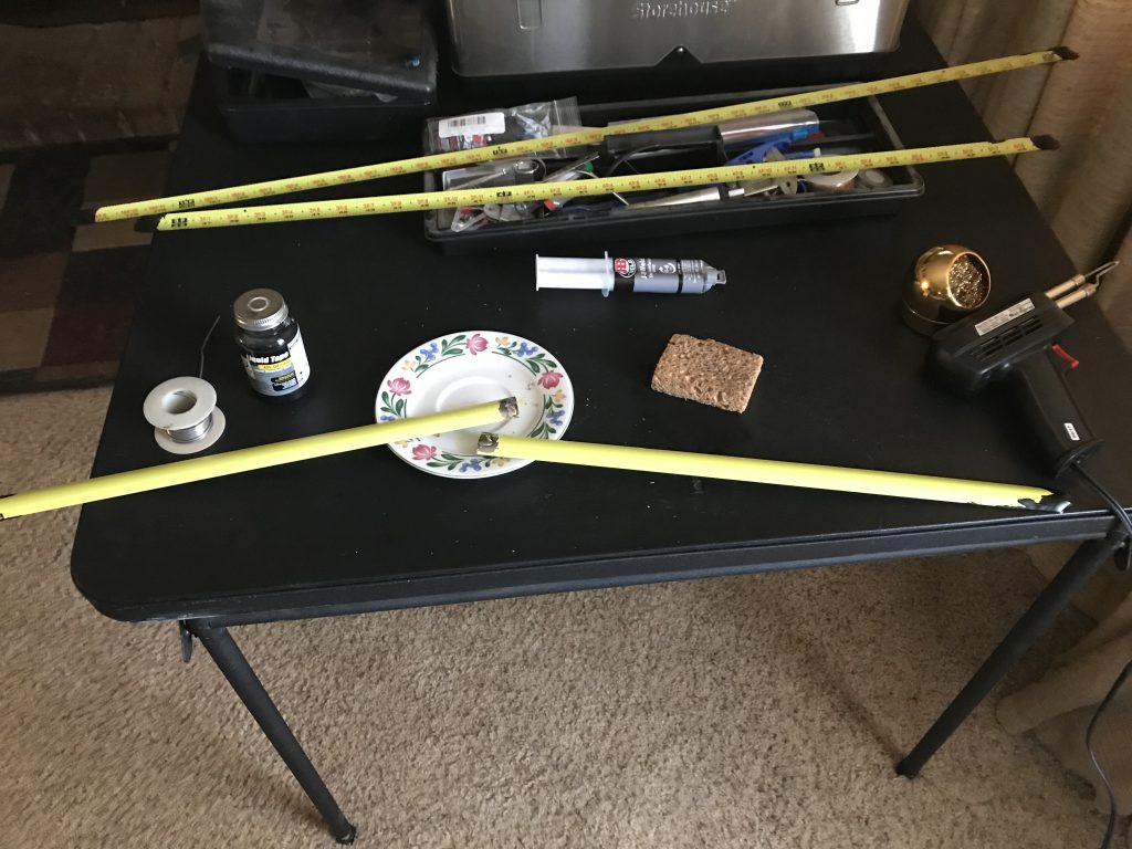
Used a very old roll of rosin core lead solder and a 250 watt soldering gun to get it to “take” the solder.
By tinning the measuring tape now, it will be far easier to solder on the (pre-tinned) hairpin match and coaxial cable later on.
Yes, it’s as messy as it looks in the photo, the “spatter” is from the tape springing back into its curved shape when I released it from the pressure of the soldering gun.
In this photo I haven’t trimmed the rubber “spurs” off with scissors yet, but you get the idea – no need for exposing anyone else to those sharp edges. I will go over each end again with RED liquid electrical tape just to make them easier for bystanders to see and avoid.
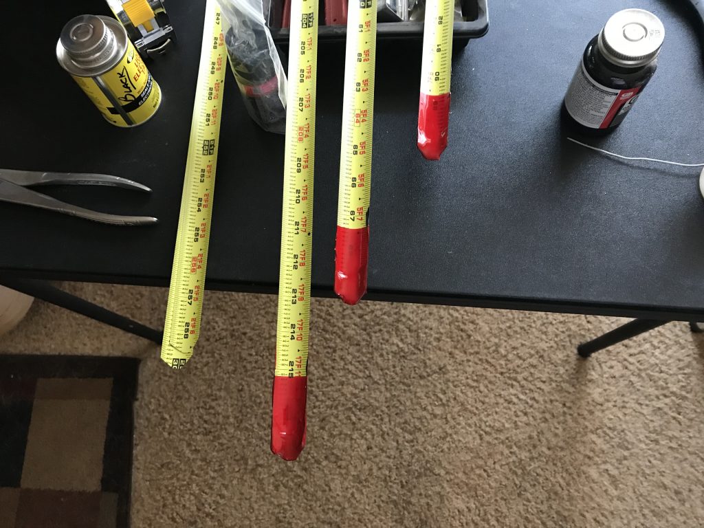
Bought a can of RED liquid electrical tape and dipped each element’s end into the can a single time, covering the black and making them a lot more visible to bystanders. (Hope) I am certainly pleased with the result.
One thing I should mention, this product is put out under “Star Bright” Liquid Electrical Tape and it’s vapors are far stronger than other manufacturers. Make certain you have good ventilation and a fan blowing the vapor away from you, or better yet – do it outside in the shade. (Guess who read the warning label after he started the project?)
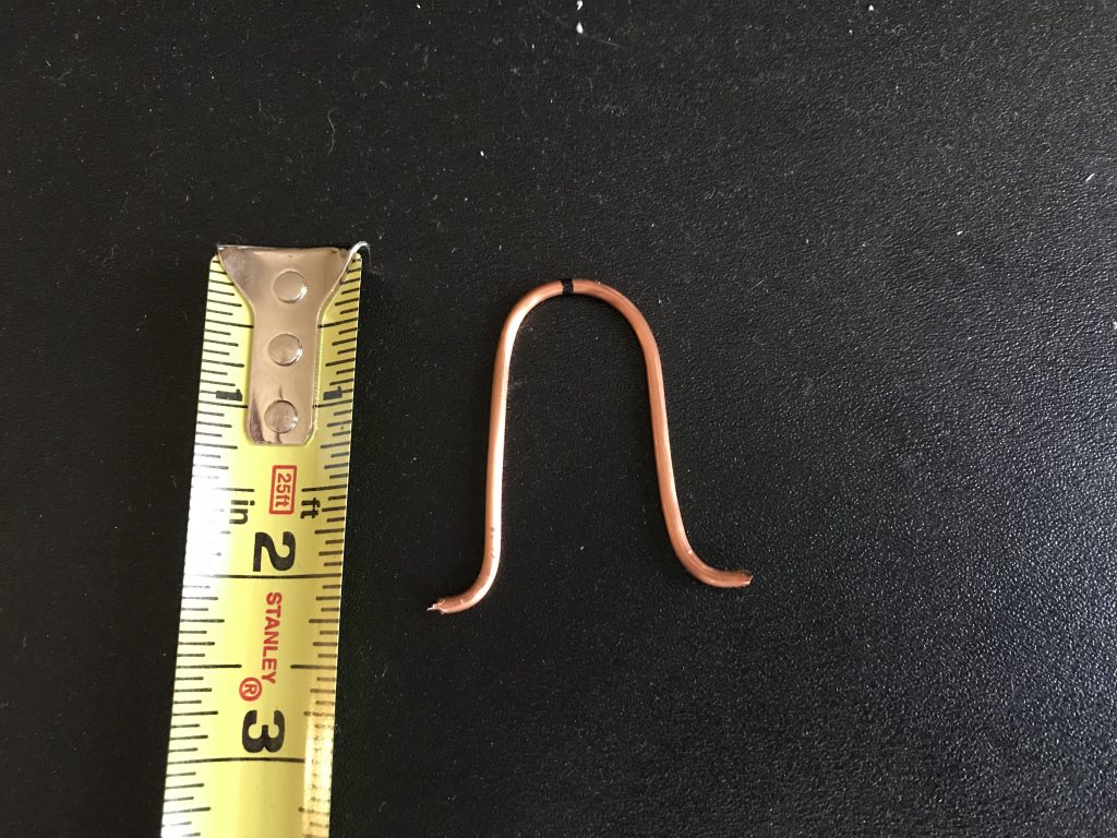
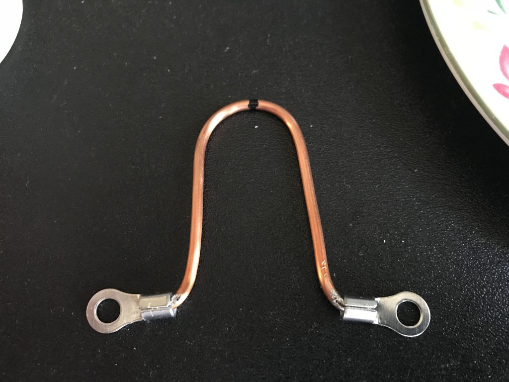
I fabricated the “Hairpin Match” out of a 5″ piece of 12 gauge solid copper wire. This seemed to be common on *all* the various web sites/different designs I’ve seen – so felt fairly confident this will work to keep the Standing Wave Ratio down when using this antenna for transmitting. I’ve been unable to understand “why” this form of matching device works – but obviously it does work indeed. You will notice I had marked the 2 1/2 ” spot on the wire prior to bending – its just a hair off of center – but doubt very much that will make any difference in performance.
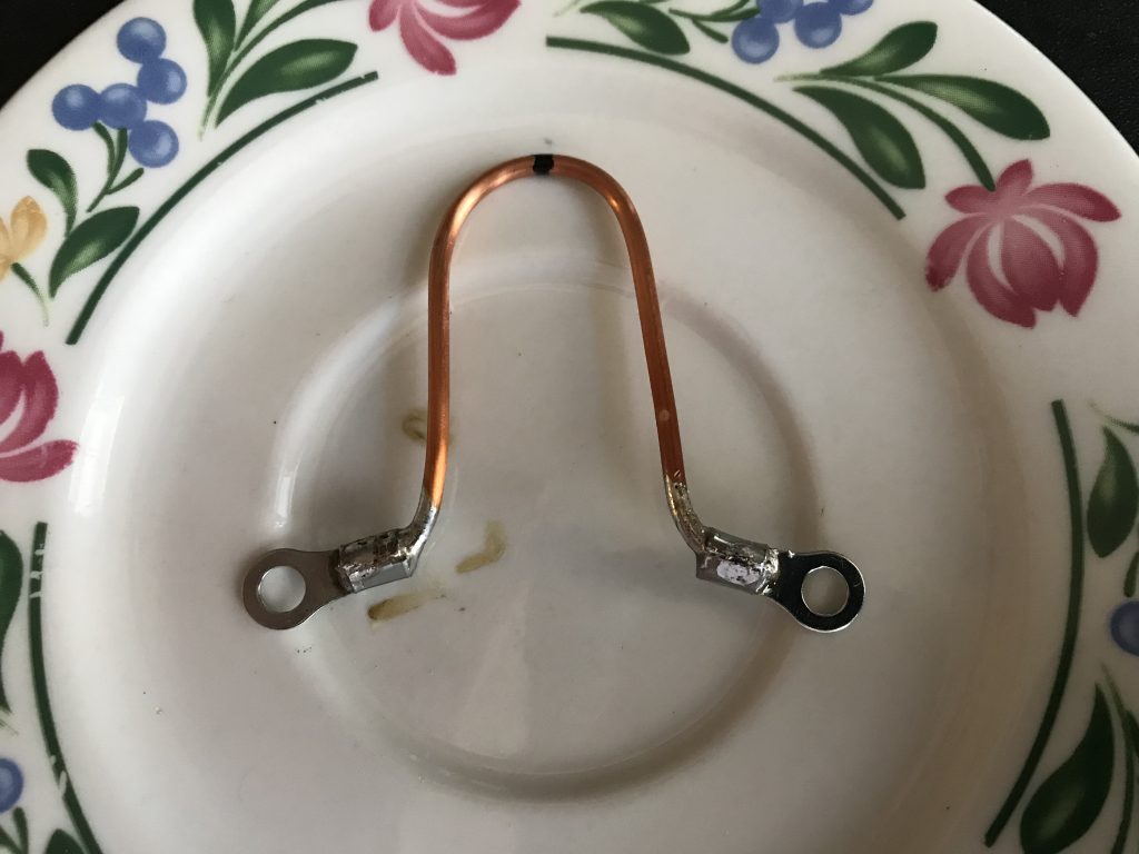
Prior to install, must tin those tips first to assure good bonding. I have not decided whether to use bare lugs as the author of the linked article did – still deciding.
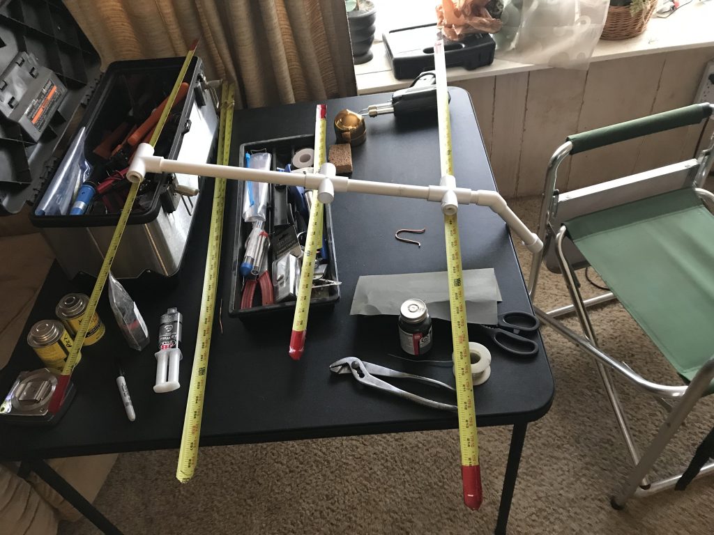
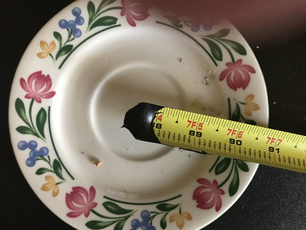
I kind of “jumped ahead” a bit this afternoon in order to show how small this antenna will really be – I will possibly need to re-install the keepers in the driven element to promote it properly folding back, but at least was able to show the overall dimensions, (nothing is glued).
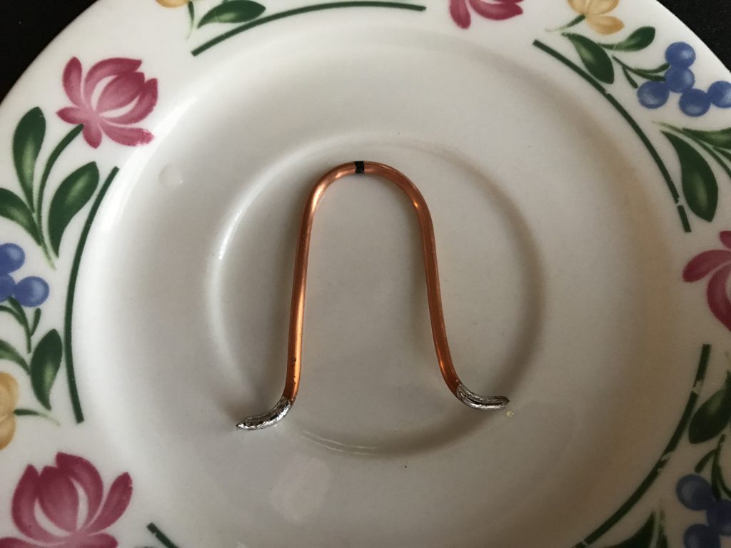
Image is pretty self-explanatory.
I have a little over 8′ of coax ready to go that was laying around from another project, with a UHF connector at the other end, (will use an adapter to go to the handheld radio).
This isn’t connected – I am just kind of toying with the idea of following what the original author did on his – it really wouldn’t be much of a bother to add the lugs – of course, if I do they will be both crimped and soldered. Guess I will – but first I will be extending the tinning on the Hairpin Match a bit further to promote connecting the coax, (which is why I like to do a pre-assembly to prevent overlooking that kind of thing).
No sooner said than done – extended tinning, crimped on lug then soldered.
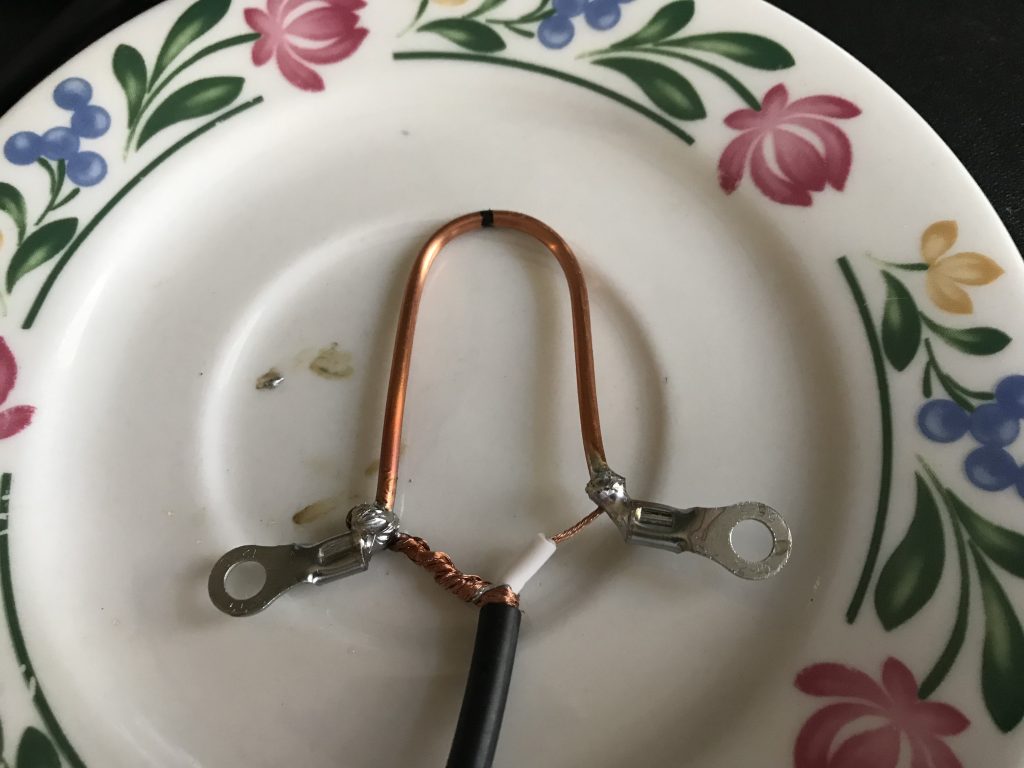
Coax is now attached – I will “tweak” the shape with my fingers later, right now all of that is *very* hot still, but thought I’d get a picture right away.
Unlike the original author, I was careful to leave some slack so the Hairpin Match could be opened wider if required – a small thing but it could be important later on.
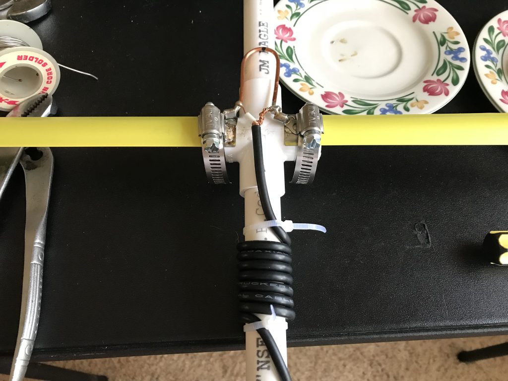
My 1 3/4″ hose clamps are a bit bigger than called for, but they are what I had handy out in the garage.
Note: 7 turns of coax around 1/2″ PVC
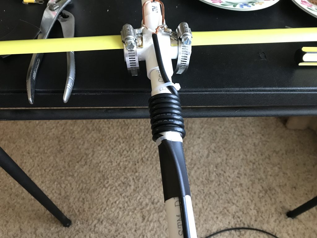
Added a short piece of 1″ shrink tubing to add a bit of stability to the coax, figure that is the high stress point.
Rather than electrical tape, I wound the 7 turn coil with 1″ gorilla tape, “just ’cause”, (adding more strength to that area and slightly improved appearance).
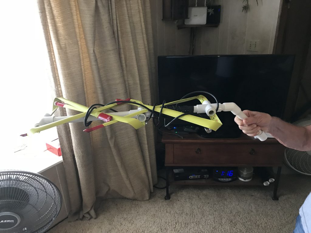
Here, Heidi is showing how it looks collapsed – I can easily just set it in the F-250’s locking toolbox back in the truck bed.
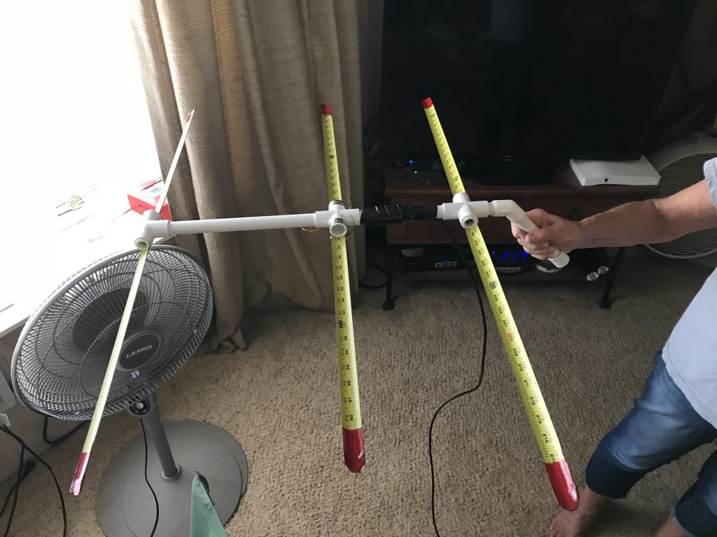
This is what it looks like just about ready for action – if/when I do this again, think I will settle for 5 – 6′ of coax, possibly shorter.
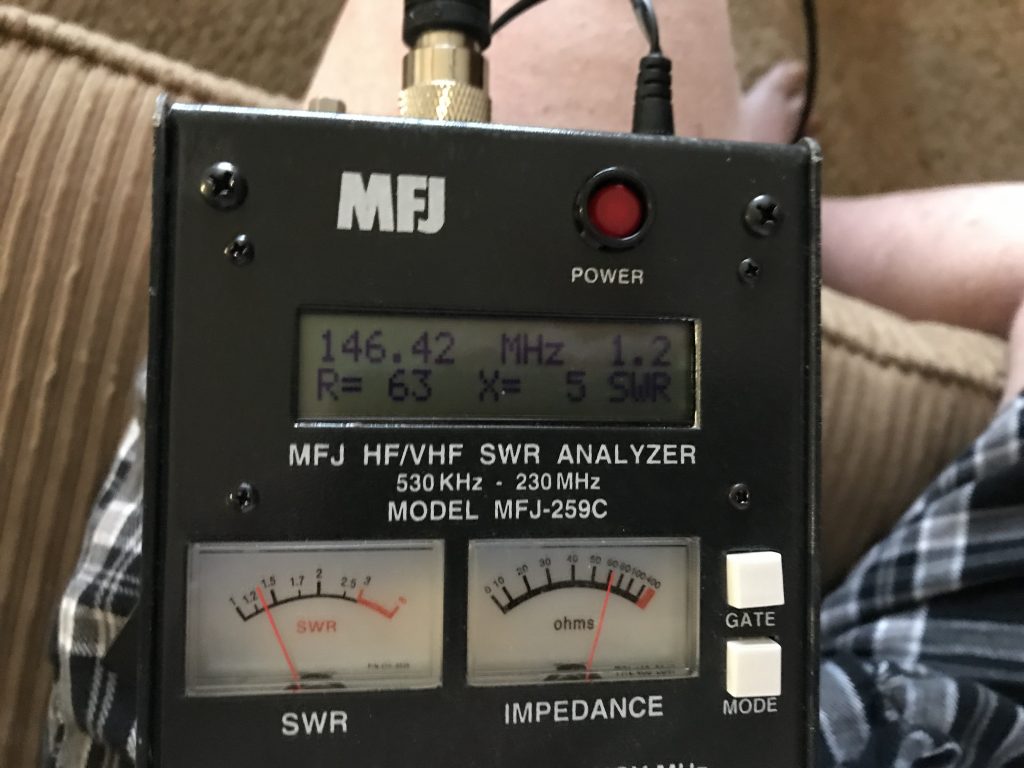
I got very lucky on the SWR – this is just holding the antenna up and aiming it toward our large picture window. Expect it will be closer to a 1:1 match when taking outside – regardless, I’ll not mess with trying to “tune” it until there is a need to do so. Happy, happy, happy with this first measurement.
Editor’s Note: After almost two years, this little antenna project has been very satisfying. Guess one of these days I will take time to actually glue it together – up to this point friction has been enough to hold everything together except the “handle” and a turn of electrical tape took care of that. 😉
While designed primarily for receive RDF, the low SWR, (near 1:1 on VHF and very workable on UHF), was quite a bonus. The gain from the little Yagi and our old FT-60 handheld can fool someone into thinking I am talking from a base station or powerful mobile rather than a portable handheld unit.
To date, I have not tried using it with any digital modes, but you can bet that will be done in future. I also want to make another of these, possibly longer with more elements and a coaxial “extension” cable, that might be useful attached to a push-up mast for voice/digital on VHF/UHF.
73, de dave/W6TUX