Ham Project – PiGate RMS
This event occurred Feb 13, 2018
I’m going to start this post by saying there is *nothing* exciting about sending an email in the times we live in – until you can’t… Then it suddenly can become *very* important depending upon your circumstances. The Internet does go down – when it does, Hams have a means of sending email via radio on to a station that *does* have Internet access and it goes on normally from there.
Well, I started out to build a simple PiGate – see www.pigate.net – then learned a friend from our Ham Club “Lou” KM6ENA who is retired USMC is building one – so I decided to move on to a PiGate RMS, (Radio Mail System), and that way he could connect his Pigate to my RMS via VHF Radio – and I would see that the “Mail” went onto the Internet.
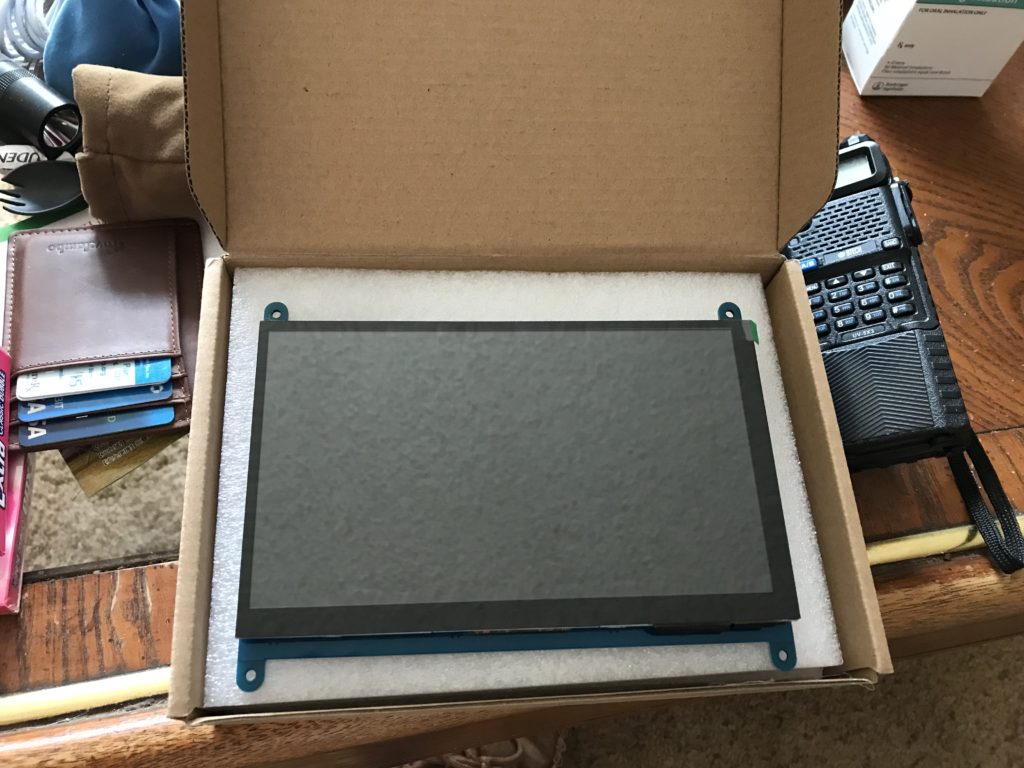
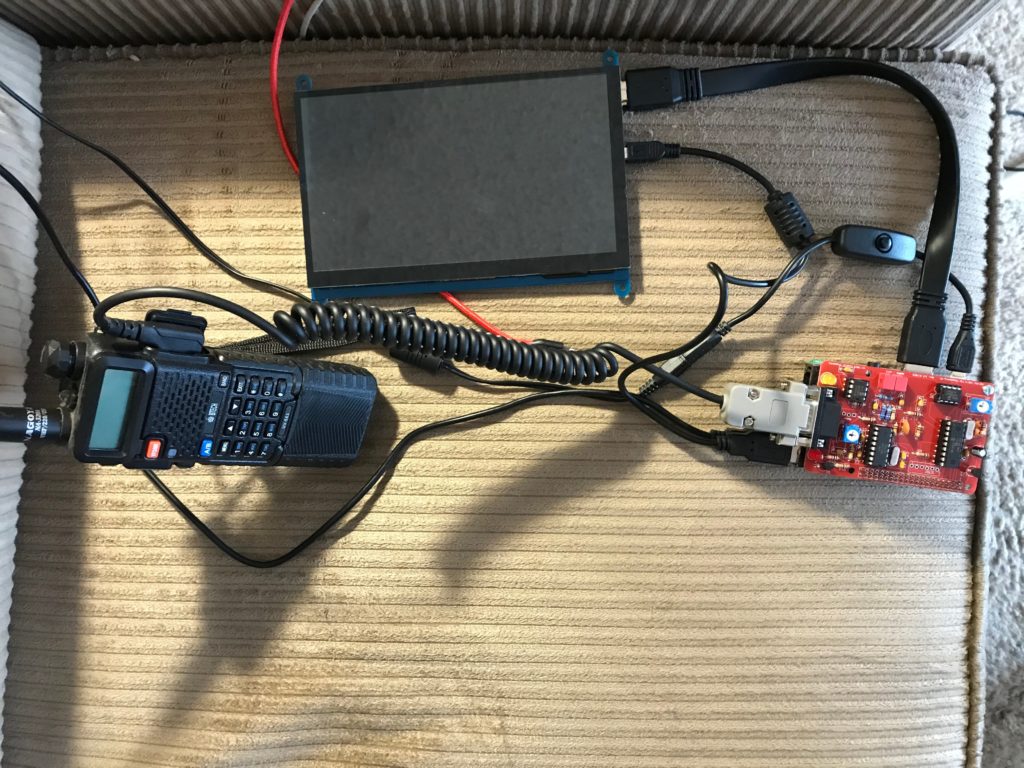
This picture shows a 7″ HDMI touch-screen from Amazon.com – eventually, I will probably go with something a bit smaller and use this screen for yet another project.
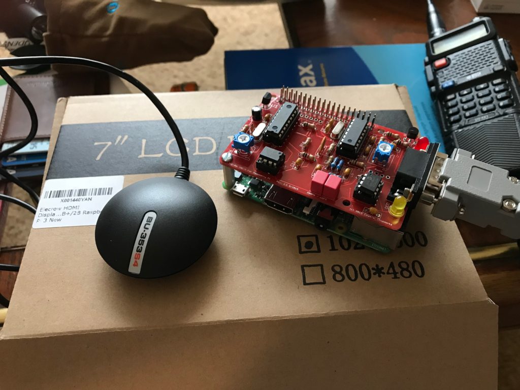
Here we see a USB GPS receiver on the left – on the right is a Raspberry Pi 3.0 single-board computer on the bottom – with a “TNC-Pi2” mounted on top. The gray connector on the right is a communication cable that will go to a handheld radio.
“TNC” means “terminal node controller” and is a device used by amateur radio operators to participate in AX.25 packet radio networks. Email messages will be passed between the radios/nodes – then the RMS will pass them on to the Internet itself for normal routing.
What you see in this picture, plus the PiGate Software, would comprise the key elements for a “PiGate Node”. I will be changing it over to PiGate RMS software, adding a display (and eventually a wireless mouse and keyboard), to hopefully end up with a fully functional PiGate RMS unit.
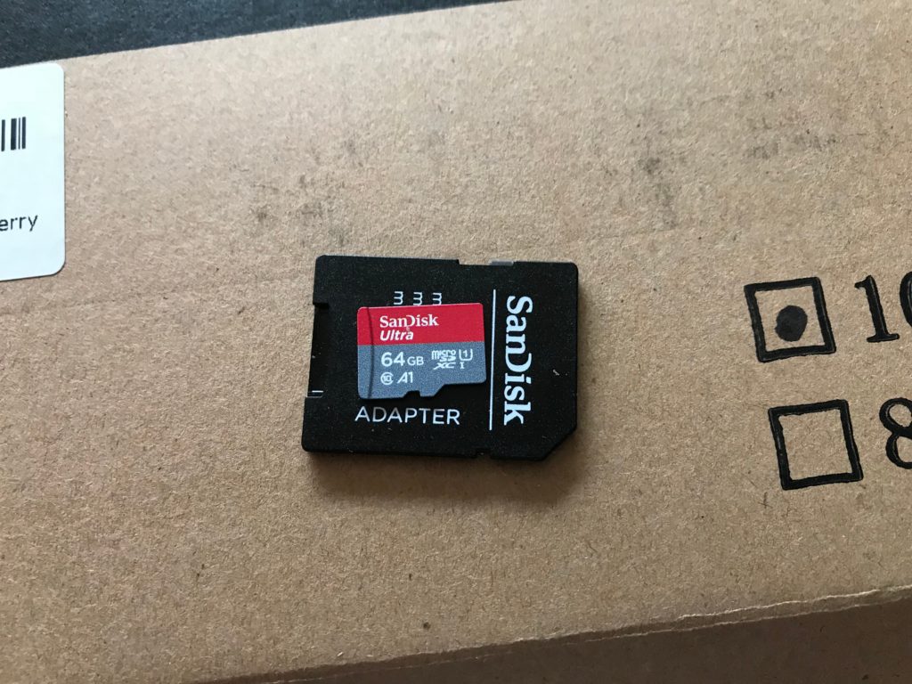
I “thought” I was going to use a 64 Gig SD card for this, but decided it was overkill and wound up using a 32 Gig card.
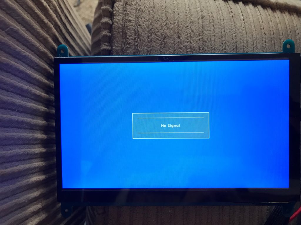
Hmmm… No display – will research this problem tomorrow, obviously a configuration thing.
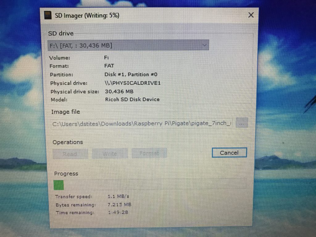
You absolutely *have* to have the SD card set up with FAT format to work with the Raspian operating system.
This is all of the main components , (you cannot see the GPS receiver in the picture). To get it configured and operating, I will be using a wired USB Mouse and keyboard – but will end up with a wireless keyboard and mouse for the actual setup.
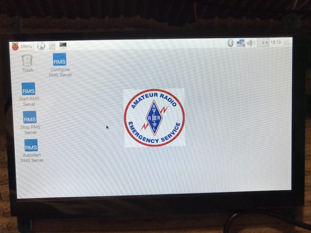
After a night away from this project, (spent all morning on our 2017 Tax returns), I overcame the configuration problem with the display by editing the “config.txt” file in the root directory of the SD card. (I used Notepad++).
What was required was to un-comment the line that said “hdmi_force_hotplug=1” then insert the following at the bottom of the file:
max_usb_current=1
hdmi_group=2
hdmi_mode=1
hdmi_mode=87
hdmi_cvt 1024 600 60 6 0 0 0
After saving the changes, put the card back in the Pi 3.0, booted it back up and Eureka!
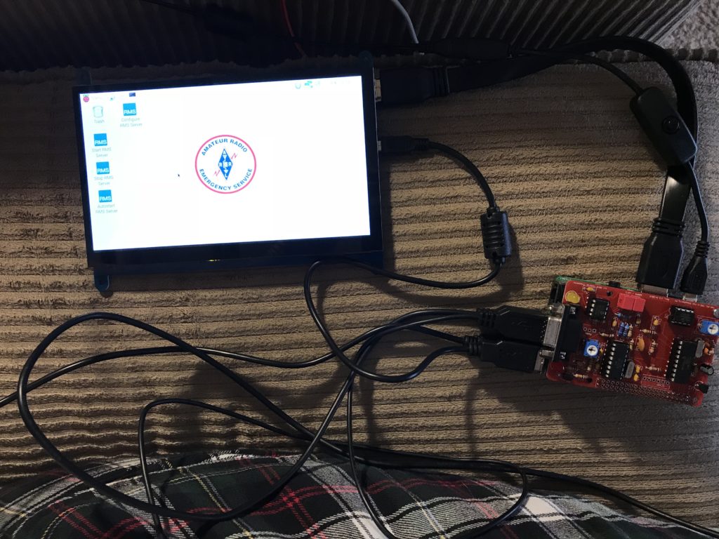
Another shot of it setting next to me on the couch – this unit will be *very* compact and portable, considering its capability.
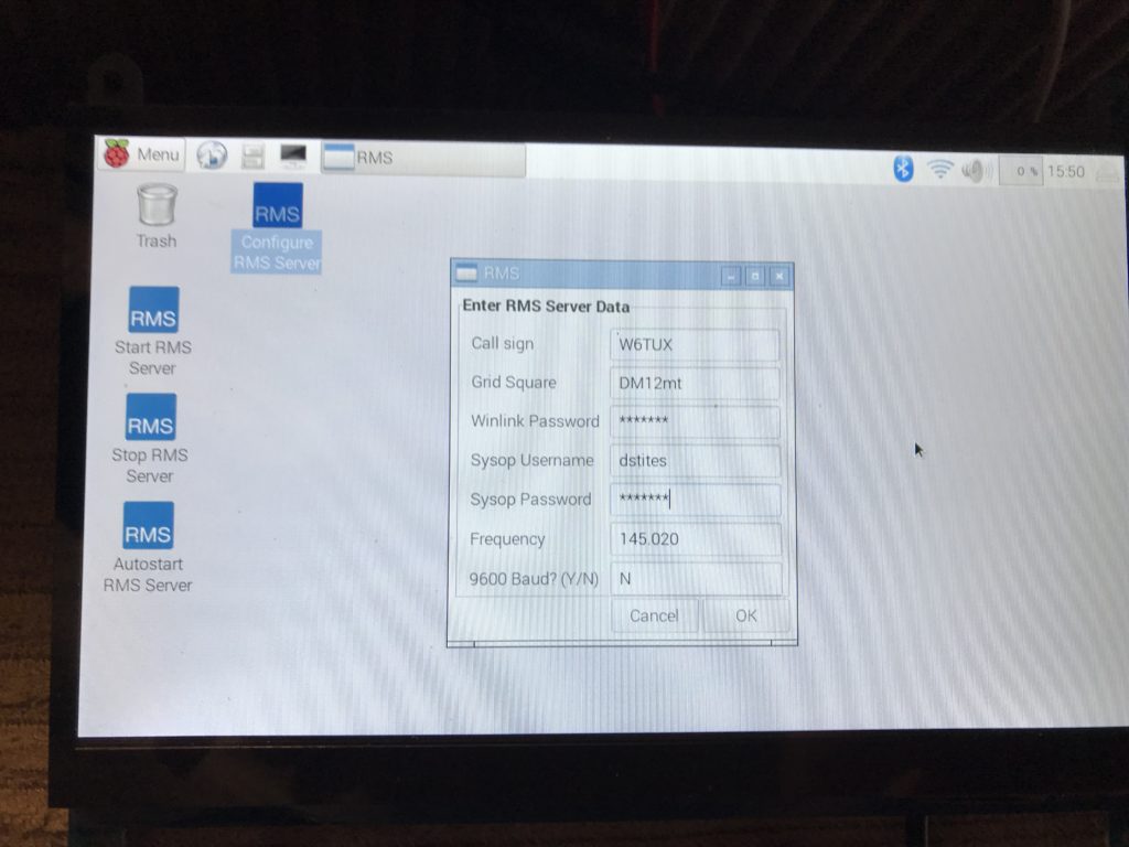
Once you have an account with the folks that run the Winlink system, this is really all that is necessary to get the RMS going. There is more to do, but after saving this (with real passwords typed in), the RMS server started with no problems and established Internet communication with the Winlink system. (Note: I inserted the series of “stars” in place of my passwords so you could see that screen).
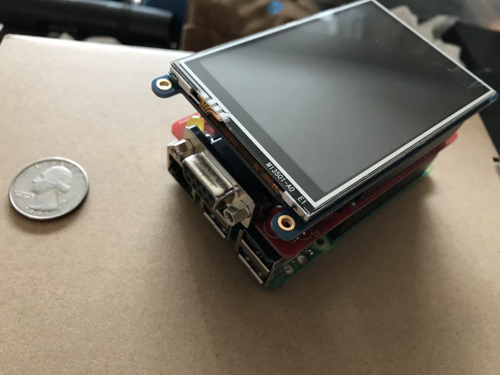
Thursday, Feb 15th, 2018 – received a tiny little 3.5″ TFT screen with a resistive touch-screen. I will need to do a little research and some more configuration on the operating system, but this is the display I want to wind up using when our PiGate RMS is ready for field use. I did attach it to the TNC-Pi2 board and power it up long enough to see its back light came on. Do have some physical modification to do, (removing some extraneous pins that will not be used by this system), but it fit well enough to satisfy me. This whole thing will eventually be encased in a custom (3D printed) case I will have to order.
Thought I would take this opportunity to place a Quarter next to it to give you a better idea as to just how tiny this project is.
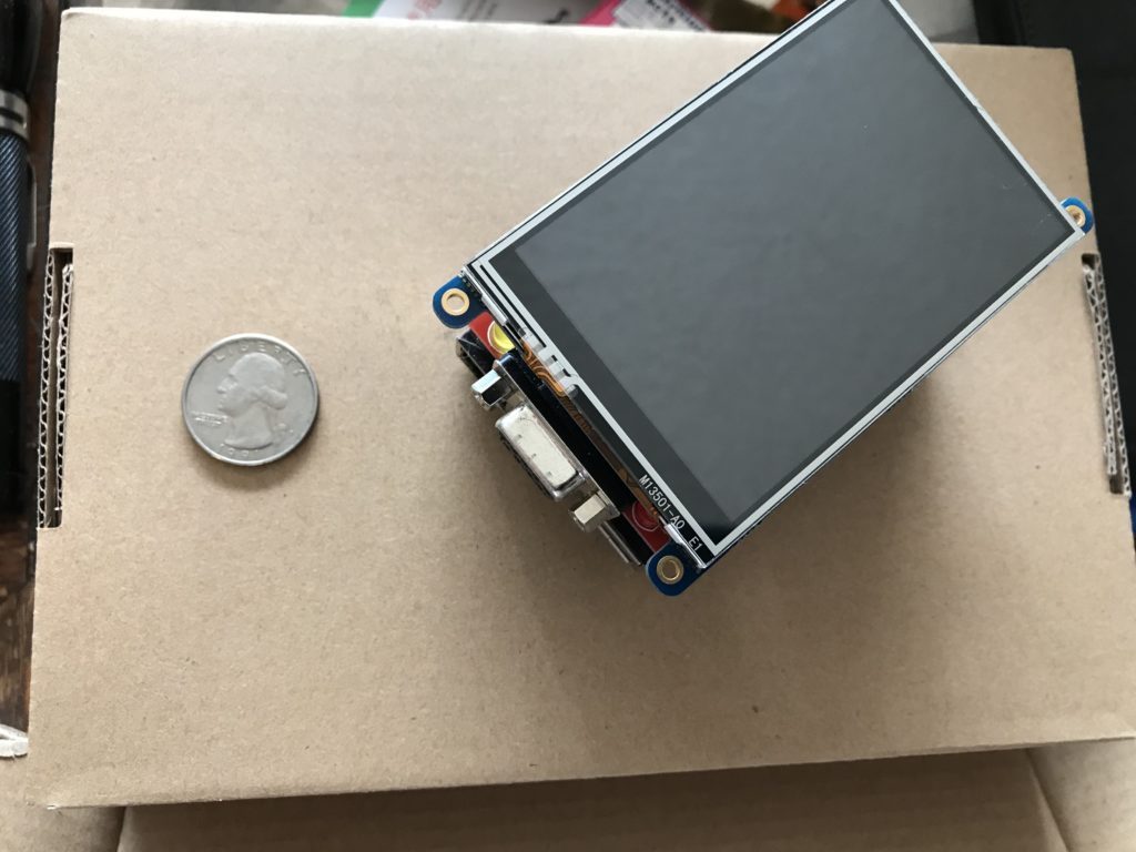
Our PiGate RMS with the 3.5″ display attached. Very soon, will be ordering a red case for it as this project comes closer to fruition.
Still Thursday the 15th, found the instructions I needed to activate the little 3.5″ display on the Adafruit web site.
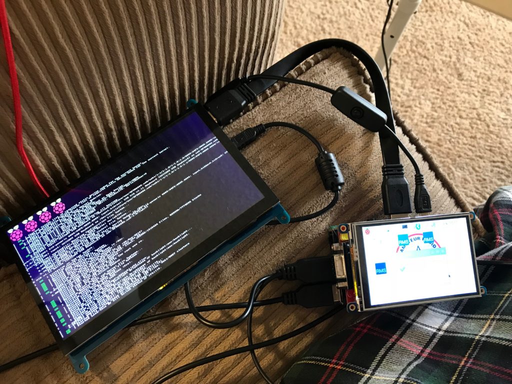
I used the 7″ HDMI monitor to edit the system and download the necessary modified kernel, etc. from Adafruit. Installed it, rebooted and the picture shows the positive results.
I did a system shutdown, powered down and unplugged the HDMI display from the Raspberry Pi 3.0 HDMI jack – also removed its USB cable that provides power to the HDMI screen.
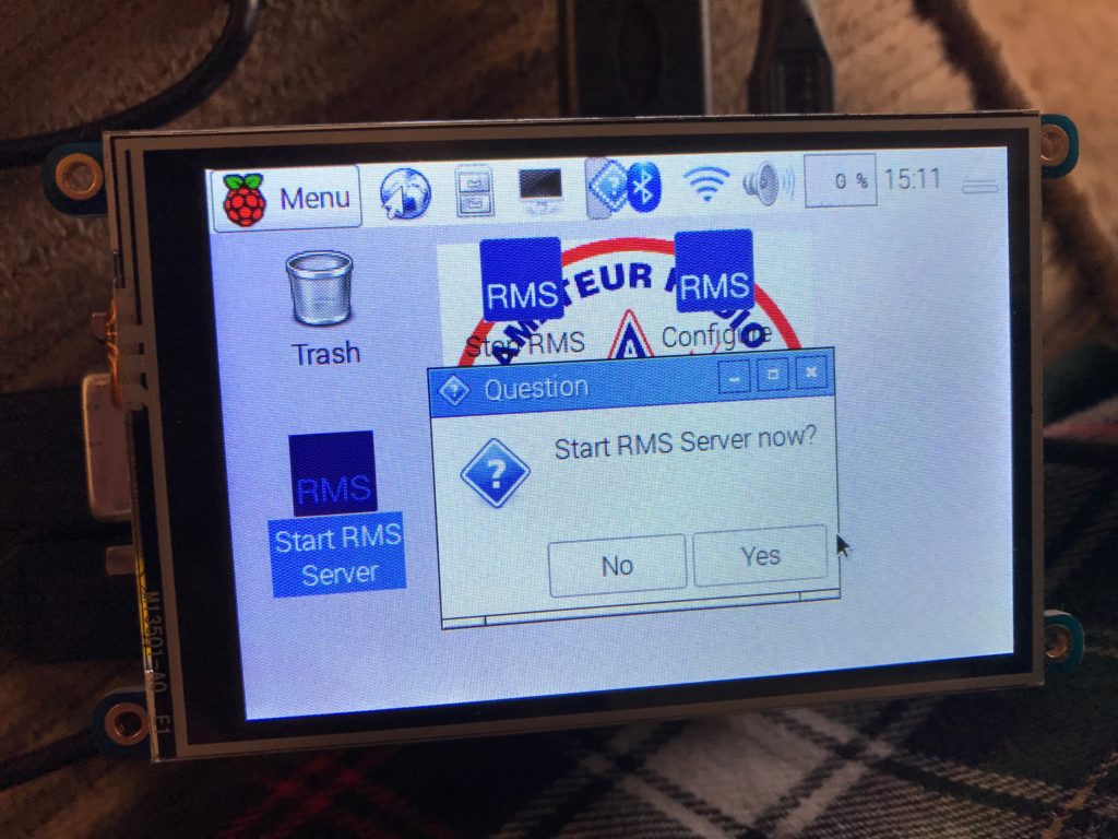
Powered the PiGate RMS back up – observed it booting – used a wired mouse to double-click on “Start RMS Server” and this picture was the result a confirmation popup. I could then click or poke “Yes”.
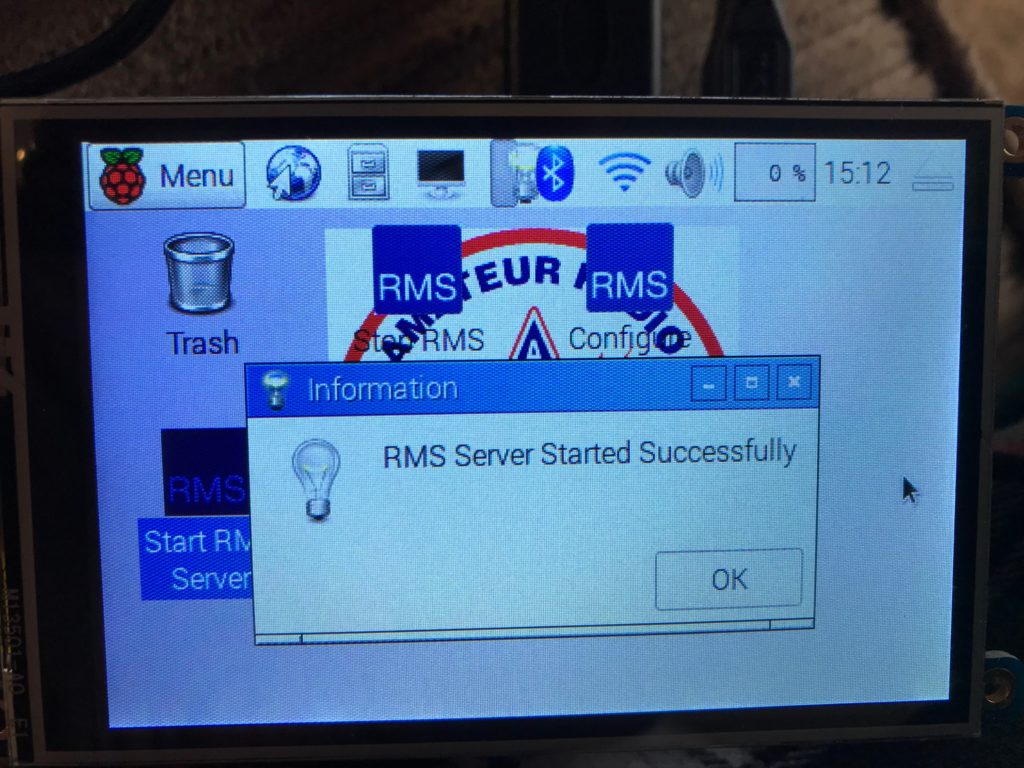
EUREKA! Its alive! Once again, this picture is a lot larger than the actual 3.5″ screen.
Showed this to Heidi and she immediately let me know it was time to order that protective case to put all of this in. Will do so this afternoon.